Installation
Rack mounting
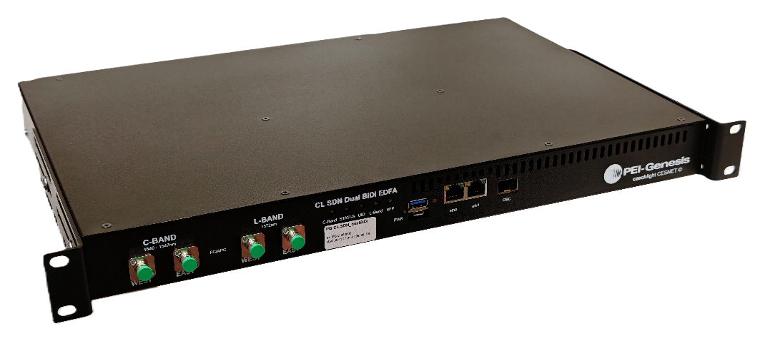
The unit is 1U high, 19” wide and 295 mm deep and mounts in a standard telecommunications rack.
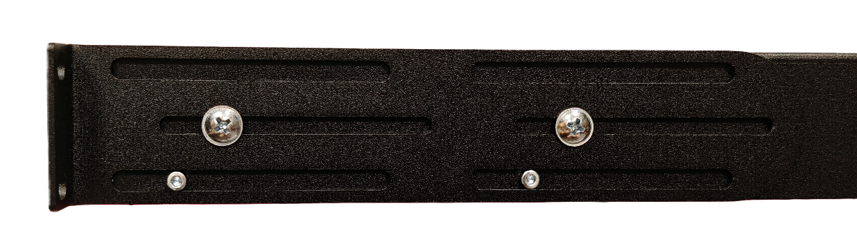
The mounting depth can be adjusted by loosening the side screws on the 19” mounting brackets.
Power supplies
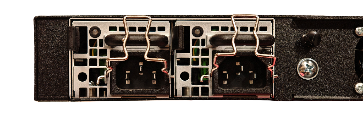
The redundant power supply modules are on the rear panel. They have no power switches.
AC version: 90–264 V AC, 47–63 Hz
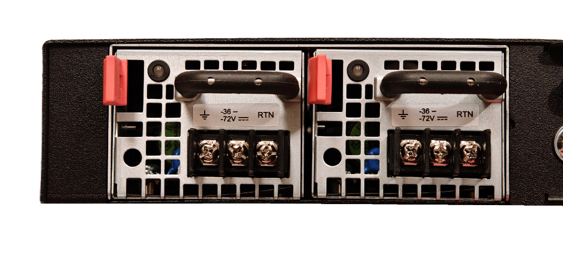
DC version: −36 to −72 V DC (nominal −48 V)
Maximum power consumption: 90 W
The device runs with one AC and one DC module if needed; modules can be swapped to change the supply type.
To switch the device off completely, disconnect both power cables, open the external circuit breakers, or pull out both modules (this is allowed while running). After inserting a module, push it in until it seats fully. The module LED lights blue when the module is connected correctly.
Two AC modules, LED indicators:
DC supply, power cable wiring. The +48 V terminal is usually connected to ground, so the supply voltage is −48 V:
Fan module
The four fans are in one hot-swappable module on the rear panel.

Removal:
Unscrew the two fan screws.
Pull out the plastic pins.
Carefully remove the module.
Installation:
With the plastic pins pulled out, slide the module into the chassis with gentle pressure so the pins line up with the holes.
Push the plastic pins into the chassis.
Tighten the two mounting screws.